
Look up! It’s a bird. No, it’s a plane. No, it’s a tower crane! That’s the official term for a crane (sometimes called a ‘derrick’) placed onto under-construction skyscrapers. But how do they get there, and how do the workers raise the crane after each floor is completed? Here, we will delve into the intricate steps involved in accomplishing this amazing engineering feat.
The Jump
Raising cranes, technically called “crane jump” or what construction workers call “jump the crane,” is a fascinating engineering feat that involves meticulous planning, specialized equipment, and skilled labor.
Although this sounds sophisticated, it is a process that is done on a routine basis, especially in cities like New York, where skyscraper construction is a daily routine.
Jumping the crane is a crucial step for facilitating the construction of tall buildings efficiently and safely.
Where’s My Crane?
The first step is selecting the appropriate type of crane for the job. Below is a list of the major types of cranes used in construction.
Mobile Cranes
Mobile cranes, as the name suggests, are mounted on tracked vehicles, allowing them to be easily transported to different locations.
Crawler Cranes
These cranes use tracks instead of wheels, providing mobility on uneven or soft ground surfaces. They are often used in heavy-duty lifting operations such as bridge building and equipment installation.
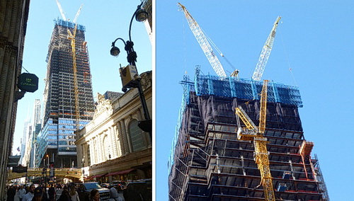
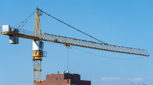
Tower Cranes
Most famous for the construction of tall buildings, especially supertalls.
Overhead Cranes
Also known as bridge or gantry cranes, they are installed on elevated runways or gantries within a building or industrial facility and are commonly used in manufacturing and warehouses.
Jib Cranes
These compact lifting devices with a vertical mast or pillar are commonly used for lifting materials in workshops, loading docks, and assembly lines. Not to be confused with the jib erected to a tower crane on skyscrapers.
Telescopic Cranes
These machines contain telescoping sections that can extend or retract to adjust the reach and lifting capacity.
Floating Cranes
These are specialized cranes usually mounted on barges, allowing them to operate on rivers, lakes, or ports. They are used for lifting heavy loads onto ships, offshore construction projects, and marine salvage operations.
Loader Cranes
Also known as knuckle boom cranes, loader cranes are equipped with hinged booms that resemble knuckle joints. This design allows the crane to fold and unfold, enhancing maneuverability and reach. Loader cranes are commonly used for loading and unloading cargo.
Skyscrapers Choice
From the choices above, the Tower Crane is used for skyscraper construction. It is characterized by its tall vertical mast and horizontal boom, which can rotate to lift and move heavy loads across the construction site. This makes it the perfect choice for the construction of tall buildings.
Assembling the Crane
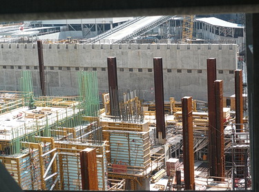
Once the crane type is chosen, the construction team begins assembling the structure on the ground. This typically involves erecting the tower mast section by section, securing it with bolts or pins, and attaching the horizontal jib or boom. Each crane section is carefully hoisted into position using smaller cranes or hydraulic systems.
As the crane assembly progresses, special attention is paid to ensure the stability and structural integrity of the crane. Counterweights are strategically placed to balance the crane’s load capacity and prevent tipping. Additionally, anchoring systems, such as tie-downs or concrete footings, are installed to secure the crane to the ground and provide stability during operation.
Safety measures are paramount throughout the crane-raising process. Construction workers receive thorough training on its assembly, and strict safety protocols are enforced to prevent accidents and injuries. Quality control inspections verify that each crane component meets safety standards before being put into service.
Lifting the Crane into Position
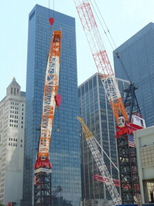
Once the crane is fully assembled and tested, it can be hoisted into position. This is typically accomplished using hydraulic jacks or a climbing system that incrementally lifts the crane to the desired height. As the crane ascends, additional mast sections may be added to extend its reach as the building grows taller.
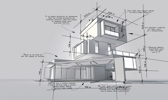
Installing the crane at the correct location maximizes its efficiency and effectiveness. Engineers carefully analyze factors such as building layout, wind patterns, and logistical considerations to determine the optimal placement for the derrick. This ensures the crane can reach all construction site areas while minimizing interference with other construction activities.
All Set
Once in position, the crane becomes an essential tool for the construction process, lifting materials, equipment, and personnel to various building levels. Skilled operators control their movement with precision, coordinating with ground crews and construction workers to safely transport loads to their designated locations.
As the skyscraper’s construction progresses, the crane may need to be modified or repositioned to accommodate changing project requirements. This could involve adding or removing mast sections, adjusting the boom length, or relocating the crane to a different part of the site. These adjustments require careful planning and coordination to minimize downtime and ensure continued productivity.
On Top of the World

Once assembled and set into place, the lifting begins, which can be steel beams, concrete sections, or other large, heavy items.
The Take Down
Eventually, as the skyscraper nears completion, the crane will be disassembled in a reverse process, as it was erected. Each component is carefully lowered to the ground using hydraulic systems or smaller cranes and dismantled for transport to the next construction site or storage facility.
Conclusion
If you live in a big city like Chicago or New York, you no doubt have seen these tower cranes in action. Now, you can appreciate the complexity and intricate process needed, along with the skilled labor and specialized equipment.
From selecting the right crane for the job to safely assembling and operating it on the construction site, every step is essential for ensuring the successful completion of tall building projects. So, the next time you look up at a skyscraper, you can credit the tower cranes and the construction workers who put it all together.